
Gas Lift Installation
Use the gas Lift Installation job to model the impact of gas lift on well performance as well as the effect of recycling lift gas in the production system.
Whenever you add a Gas Lift Facility, an accompanying Gas Lift Installation job is created along with a Facility Construction job. This GL job cannot be deleted while the facility or the construction job exist; therefore, you do not need to create another GL job unless you wish to use the same facility for more than one GL job.
How can I define the impact of Gas Lift on well performance and facility throughput?
In the left part of the tab you must choose the Gas Lift facility which will provide the gas. This facility must already have been created in the Surface Layout. If you have already connected wells to this facility they will appear in the list box below; otherwise you must define the wells now and the list will be automatically updated in the Surface Layout.
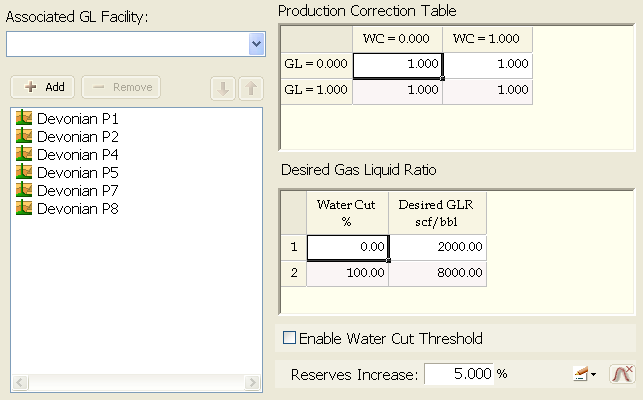
The right part of the tab has to do with the impact of Gas Lift in the production of the selected wells.
The Production Correction Factor table allows you to model the impact of Gas Lift and lack thereof on production. The production corrector factor is obtained as a function of Water Cut (WC, 0 = 0% water, 1 = 100% water) and lift gas available (GL, 0 = no gas available, 1 = all required gas delivered). As the simulation proceeds, the application calculates the WC corresponding to the present timestep, and then what lift gas is available at that point, so as to obtain the cell with the right correction factor. The theoretic production for that timestep will be multiplied by that factor, thus yielding the actual production including Gas Lift impact. Intermediate values are calculated by linear interpolation, but you can add rows to either column to gain precision.
Desired Gas-Liquid Ratio / Desired Gas Rate: Use the  button to switch between:
- Using a table to enter the variations in required Gas-Liquid Ratio (Desired GLR, used in the first table) in scf/bbl according to the Water Cut. In this case WC is expressed as a percentage, and a fixed gas volume for each WC is entered; this fixed gas volume includes the sum of lift gas and produced solution gas. You can also add rows here.
- Entering a single value for a Gas Rate independent from Water Cut and Production.
When gas lift is used, the simulation timestep is automatically reduced to one day in order to ensure a stable simulation. This generally results in a significant increase in simulation time.
In the Simulation Graphs, gas-lift gas will be included in the total gas routed though facilities which received production from gas-lifted wells. However, Gas Lift is modeled as working cyclically: the gas-lift gas is not added back to the wells under gas lift so the well production profiles will not include gas-lift gas.
Activate when: Check this box if you wish to activate the Gas Lift only when each well meets a given condition. If left unchecked, the Gas Lift will be activated as soon as the installation is complete.
Reserves Increase: Enter here the percentage of reserves increase as a result of the Gas Lift installation. Every well's performance curve will be normalized to include the reserves increase when Gas Lift is installed in the well.
Installation vs. Activation
PetroVR allows you to distinguish between installation and activation of a Gas Lift Installation job.
Installation represents the fact that the Gas Lift equipment has been completed and is ready to start working; it is determined by the duration of the job.
By default, the end of the installation coincides with the activation, which is the moment the Gas Lift system starts working; but you can instruct PetroVR to activate Gas Lift on a well only when a given Water Cut is reached for that well.